Crystal Oscillator Drive Power Testing and Calculation Passive crystal oscillators do not have their own oscillation function and must rely on external circuitry to operate. Excitation power refers to the energy required to drive the crystal oscillator. High drive power degrades the crystal's characteristics (such as abnormal frequency jumping, abnormal internal resistance jumps), and may even damage the crystal; low drive power sometimes increases the crystal's internal resistance, which may result in intermittent, non-reproducible oscillation when the oscillator is restarted. Properly matching the excitation power is a core element in ensuring the long-term stable operation of the crystal oscillator.
Calculation Formula The formula for calculating the drive power DL is:
DL = I² × ESR
Where: I is the effective value of the current flowing through the crystal oscillator (unit: A/mA), ESR is the equivalent series resistance of the crystal oscillator (unit: Ω), and DL is measured in watts (W), often expressed in microwatts (μW).
Test Method Equipment Preparation: PCB board, crystal oscillator (with equivalent circuit constant data), oscilloscope, current probe.
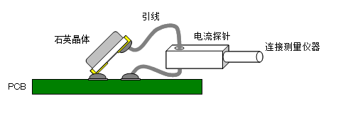
Circuit Connection: Desolder one side of the crystal oscillator pins, connect a lead in series with a current probe, and resolder it back onto the PCB, ensuring circuit integrity.
1. Measure Current Waveform: Power on the PCB and observe the crystal oscillator current waveform with an oscilloscope to confirm it is a sine wave or a similar waveform.
2. Read the Effective Current Value: Read the effective current value (RMS).
3. Calculate Drive Power: Calculate the drive power using DL = I² × ESR, where ESR can be measured using professional equipment to determine the equivalent value of the crystal oscillator unit. Result Judgment: Compare the calculated DL with the maximum drive power in the crystal oscillator datasheet to ensure DL does not exceed the maximum value.
Precautions:
Measurement Accuracy: Use a high-precision current probe and oscilloscope to ensure accurate measurement results.
Circuit Integrity: When modifying the circuit, keep leads as short as possible to avoid introducing additional interference or parasitic parameters.
Waveform Confirmation: Ensure the crystal oscillator current waveform is a sine wave. If the waveform is distorted, check for overdrive or other problems in the circuit.
Safe Operation: Avoid short circuits or overcurrent to prevent damage to the crystal oscillator or circuit components. By following the steps above, the crystal oscillator drive power can be accurately tested and calculated, ensuring that the crystal oscillator operates within a safe range and guaranteeing the stability and reliability of the circuit.