In electronic circuit design, every parameter of a crystal oscillator is crucial to the product's success—even a 0.1ppm error can derail an entire board. These seemingly basic terms are the invisible hurdles hardware engineers must overcome daily.
This article will begin with common terminology and explain key concepts such as crystal oscillator materials, structures, and circuits, turning these "hurdles" into "stepping stones."
Due to its length, it will be divided into two articles. This is the first part, covering the following topics:
· Quartz materials and frequency control products
· Piezoelectricity
· Quartz crystal cut types
· Vibration modes
· Frequency-temperature characteristics
· Equivalent circuits of crystal resonators
> Quartz materials and frequency control products
Quartz is a piezoelectric crystal (SiO₂) widely used for frequency control in electronic devices. Its main products fall into two categories:
Bulk acoustic wave devices: such as crystal resonators, crystal filters, and clock oscillators (such as Pierce oscillators and voltage-controlled oscillators). Surface acoustic wave devices, such as surface acoustic wave (SAW) resonators and filters, use interdigital transducers (IDTs) to generate high-frequency vibrations on the quartz surface.
(Figure 1) Crystalline Quartz Material
> Piezoelectricity
In a stable state, the electric dipoles of SiO₂ (silicon dioxide) are aligned along the six axes of silicon, making it electrically neutral overall. When an external electric field is applied:
The electric field applied in the direction of the dipoles: the silicon side becomes positively charged, the oxygen side becomes negatively charged, and the induced electric field balances the system.
Applying the electric field in the opposite direction (negative charge on the silicon side, positive charge on the oxygen side) causes the oxygen ions to approach each other, and their horizontal vibration frequency synchronizes with the vertical alternating electric field, with the amplitude depending on the angle between the electric field and the dipoles.
When the alternating electric field frequency matches the horizontal vibration frequency of the oxygen ions, resonance occurs, with the amplitude depending on the angle between the electric field and the dipoles. In three-dimensional devices, the electric field is provided by electrodes on the wafer surface, and the dipole direction is determined by the cutting angle. Piezoelectricity is a key physical property of quartz crystals, describing the mutual conversion between electrical and mechanical energy. Specifically:
· When mechanical stress (such as compression, stretching, or bending) is applied to a quartz crystal, its internal charge redistributes, generating a voltage on the crystal surface.
· Conversely, when voltage (or an alternating electric field) is applied to a quartz crystal, the atoms within the crystal shift, causing the crystal to mechanically deform or vibrate.
It is precisely by utilizing this "electricity-force" mutual conversion property that we can precisely vibrate quartz crystals in circuits, thereby generating stable frequency signals.
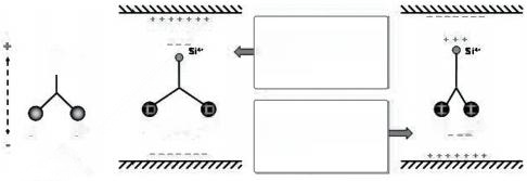
(Figure 2) Simplified one-dimensional piezoelectricity of SiO₂
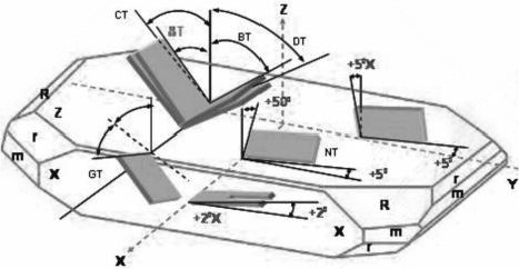
> Quartz Crystal Cut Types
Depending on the cut angle of the quartz rod, there are different types of quartz plates, such as AT, BT, CT, DT, NT, and GT cuts. These different types of quartz plates, represented by a set of Euler angles, have different available elastic, piezoelectric, and dielectric properties. These are fundamental parameters for designing quartz crystal devices. The most commonly used quartz cut types are shown in Figure 3.
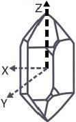
(Figure 3) Orientation angle of a Z-plate quartz crystal.
> Vibration Modes
The vibration types of quartz crystal units are categorized as bending vibration, expansion vibration, surface shear vibration, and thickness shear vibration. A schematic diagram of commonly used vibration types and cutting methods is listed in Table 1. The fundamental frequency and overtones can operate in any type of resonator. The fundamental frequency is the most commonly used, but overtones are also commonly used for thickness-type devices, as shown in Figure 4.
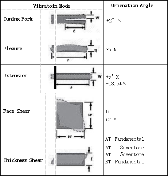
(Figure 4) Vibration Modes and Cut Angles.
> Frequency-Temperature Characteristics
Quartz products are mostly used as circuit components for frequency selection and/or frequency control, so the device's frequency-temperature characteristics are the most important parameter. This part-per-million (ppm)-level frequency-temperature stability is another advantage of quartz frequency devices, something that LCR discrete-component oscillator circuits cannot achieve in mass production. The frequency-temperature characteristics of commonly used quartz crystal cuts are shown in Figure 5.
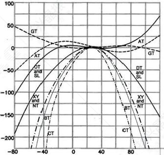
(Figure 5) Frequency-temperature characteristics of various quartz slices. The AT cut is the most popular MHz crystal cut for quartz devices. Figure 6 shows the AT-cut orientation from the top view along the +x axis.
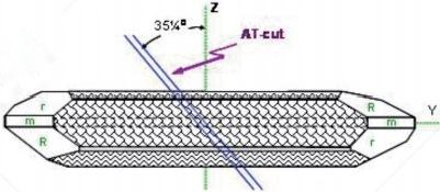
(Figure 6) AT platform positioning
Figure 7 shows the relationship between the cut angle of the AT crystal and its frequency-temperature characteristics. The results show that AT-cut quartz exhibits excellent frequency stability over a wide temperature range. Because the first and second derivatives of the frequency-temperature curve (i.e., the first and second components of the temperature coefficient) approach zero within this temperature range, its frequency variation is primarily governed by a third-order function.
△fs(i)=A1(Ti-25)³+A2(Ti-25)²+A3(Ti-25)+A4
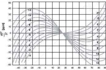
(Figure 7) AT-cut frequency-temperature characteristics
> Equivalent circuit of a crystal resonator
(Figure 8) shows simplified diagrams and symbols for metal-type and ceramic-chip resonators. When operating near the resonant frequency band, the electrical characteristics of an unloaded resonator can be approximated by a Butterworth-Van Dyke (BVD) equivalent circuit, as shown in Figure 9.
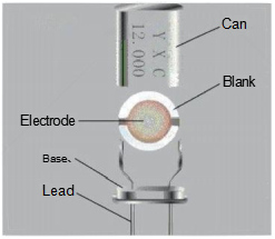
A) Metal cylinder resonator
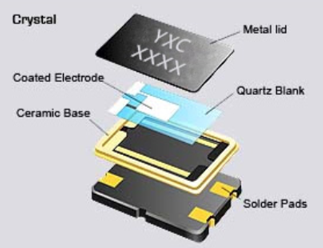
B) Ceramic patch d-type resonator
CL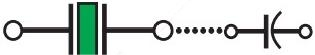
C) Symbolic crystal needle
Using the parameters shown in Figure 8, the main electrical characteristics of a crystal resonator and an oscillator composed of a crystal resonator are described below.
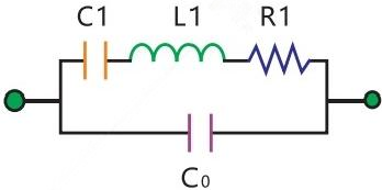
(Figure 9)
C0: Shunt capacitor
C1: Motional capacitor
L1: Motional inductor
R1: Motional resistance