Active crystal oscillators are a type of crystal oscillator. Unlike passive crystal oscillators, active crystal oscillators have their own internal IC and oscillation circuit, requiring no external circuitry to operate.
For active crystal oscillators, are you familiar with their common parameters, circuit diagrams, and wiring principles? Today, Xiaoyang will explain the active crystal oscillator circuit, pins, parameters, and wiring principles in detail.
一、Common Parameters of Active Crystal Oscillators
What are the parameters of an active crystal oscillator? The parameters of an active crystal oscillator include total frequency deviation, voltage-controlled linearity, frequency temperature stability, frequency aging rate, and power-on characteristics. Specifically, there are five points:
1. Total Frequency Deviation: The maximum deviation of the crystal oscillator frequency from the given nominal frequency caused by all combinations of specified operating and non-operating parameters within a specified time.
2. Voltage-Controlled Linearity: A measure of the output frequency-input control voltage transfer characteristic compared to an ideal (linear) function. It is expressed as a percentage of the allowable nonlinearity of frequency deviation over the entire range.
3. Frequency Temperature Stability: The maximum permissible frequency deviation within the specified temperature range, without or with an implicit reference temperature, under nominal power supply and load.
4. Frequency Aging Rate: The relationship between oscillator frequency and time when measuring oscillator frequency under constant environmental conditions. This long-term frequency drift is caused by the slow changes in crystal elements and oscillator components. Therefore, the rate of frequency deviation is called the aging rate, which can be expressed as the maximum rate of change after a specified time limit (e.g., ±10 ppb/day, after 72 hours of power-on), or the maximum total frequency change within a specified time limit (e.g., ±1 ppm/(first year) and ±5 ppm/(ten years)).
5. Start-up Characteristics (Frequency Stability Warm-up Time): The rate of change of frequency from a certain period after power-on (e.g., 5 minutes) to another period after power-on (e.g., 1 hour), indicating the speed at which the crystal oscillator reaches stability.
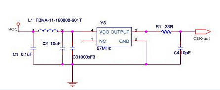
二、 Active Crystal Oscillator EMC Circuit Diagram
① R1 is a reserved matching design; it can be adjusted or the ferrite bead replaced according to experimental conditions.
② C1 is a reserved design; it can be added or adjusted according to actual needs.
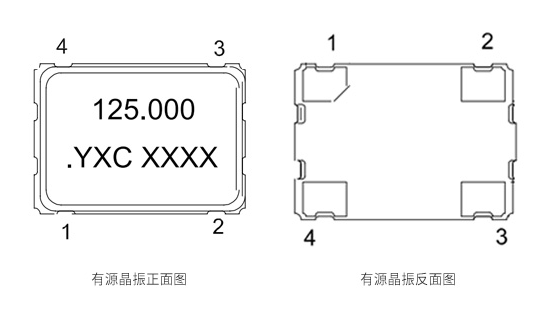
三、Active Crystal Oscillator Pin Diagram
① Square type, using a DIP-8 package; the pin marked with a dot is pin 1.
1-NC; 4-GND; 5-Output; 8-VCC
② Rectangular type, using a DIP-14 package; the pin marked with a dot is pin 1.
1-NC; 7-GND; 8-Output; 14-VCC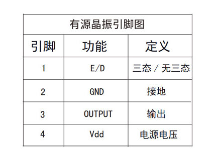
四、Active Crystal Oscillator Connection Method
Active crystal oscillators generally have 4 pins. The pin marked with a dot is pin 1. In counter-clockwise direction (pins down), they are pins 2, 3, and 4.
Common usage of active crystal oscillators: Pin 1 is floating, pin 2 is grounded, pin 3 is connected to the output, and pin 4 is connected to the voltage.
Different crystal oscillator brands or models have different wiring methods. It is recommended to confirm with the crystal oscillator manufacturer before wiring to avoid incorrect wiring that could cause the crystal oscillator to malfunction.